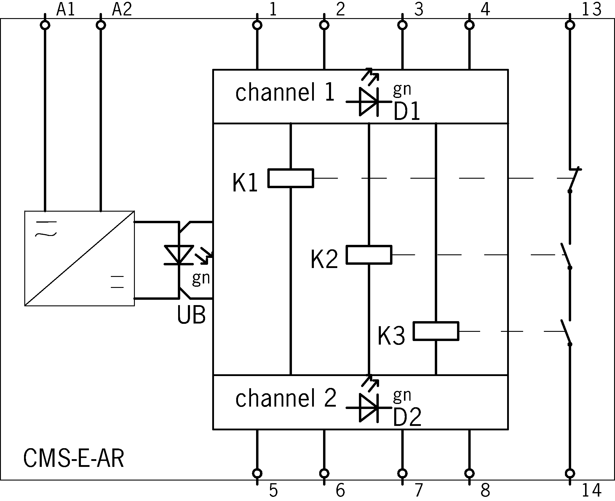
EUCHNER GmbH + Co. KG CMS-E-AR
CMS-E-AR
Технические характеристики
| LED display | 1 indicator LED Power (UB) and 2 status indicators for the read heads (D1/D2) |
|---|---|
| Напряжение питания | 0.75 A Automatically resetting fuse PTC |
| Safety contacts 13/14 | 3 A gG (External contact fuse (safety circuit) acc. to EN IEC 60269-1) |
| Connection cross section | 0.14 ... 2.5 mm² |
| Напряжение питания | 250 V |
| DC | 24 V -10% ... +10% (All the electrical connections must either be isolated from the mains supply by a safety transformer according to EN 61558-2-6 with limited output voltage in the event of a fault, or by other equivalent insulation measures.) |
| AC-1 | 3A, 250V (Max. switching current per contact) |
| DC-13 | 1.8A, 24V (Max. switching current per contact) |
| AC-15 | 0.9A, 250V (Max. switching current per contact) |
| Risk time according to EN 60947-5-3 | max. 10 ms |
| According to UL class 2 | Input: 24 V DC; output: 24 V DC |
| Electrical connection values - Safety contacts 13/14 | max. 750 VA |
| Current consumption | 70 mA |
| Degree of contamination (external, according to EN 60947-1) | 2 |
| Connection type | Connection terminals, plug-in |
| Storage temperature | -25 ... 70 °C |
| Mechanical life | 10 x 10⁶ |
| Mounting type | Mounting rail TH 35 (EN IEC 60715) |
| Degree of protection | Terminals IP20 / housing IP40 |
| Рабочая температура | 0 ... 50 °C |
| Housing | Polycarbonate (PC) |
| in compliance with | EN ISO 13849-1: 2015 ; EN 50178: 1997 ; EN 60204-1: 2006/A1: 2009 ; EN ISO 14119: 2013; EN 6100-6-2: 2005; EN 6100-6-3: 2007/A1:2011; EN 60947-5-3: 2013 |
| Secured switch-off distance s ar | 16 mm (The assured release distance s_ar corresponds to the reset distance.) |
| with center offset m=0 | min. 7 mm (Figure only applies if there is no ferromagnetic material in the vicinity of the read head and the actuator.) |
| at s = 3 mm read distance | 2.5 mm (Figure only applies if there is no ferromagnetic material in the vicinity of the read head and the actuator.) |
| In combination with read head CMS-R-BXO-05V, CMS-R-BXP-05V, CMS-R-BXO-SC, CMS-R-BXP-SC, CMS-R-BXO-05P and actuator CMS-M-BH - Secured switch-off distance s ar | 17 mm (The assured release distance s_ar corresponds to the reset distance.) |
| In combination with read head CMS-R-BXO-05V, CMS-R-BXP-05V, CMS-R-BXO-SC, CMS-R-BXP-SC, CMS-R-BXO-05P and actuator CMS-M-BH - with center offset m=0 | min. 6 mm (Figure only applies if there is no ferromagnetic material in the vicinity of the read head and the actuator.) |
| In combination with read head CMS-R-BXO-05V, CMS-R-BXP-05V, CMS-R-BXO-SC, CMS-R-BXP-SC, CMS-R-BXO-05P and actuator CMS-M-BH - at s = 3 mm read distance | 2.5 mm (Figure only applies if there is no ferromagnetic material in the vicinity of the read head and the actuator.) |
| In combination with read head CMS-R-CXA-03V, CMS-R-CXB-03V, CMS-R-CXA-05V, CMS-R-CXB-05V and actuator CMS-M-CA - Secured switch-off distance s ar | 16 mm (The assured release distance s_ar corresponds to the reset distance.) |
| In combination with read head CMS-R-CXA-03V, CMS-R-CXB-03V, CMS-R-CXA-05V, CMS-R-CXB-05V and actuator CMS-M-CA - with center offset m=0 | min. 7 mm (Figure only applies if there is no ferromagnetic material in the vicinity of the read head and the actuator.) |
| In combination with read head CMS-R-CXA-03V, CMS-R-CXB-03V, CMS-R-CXA-05V, CMS-R-CXB-05V and actuator CMS-M-CA - at s = 3 mm read distance | 2.5 mm (Figure only applies if there is no ferromagnetic material in the vicinity of the read head and the actuator.) |
| Contact status indication with LED | 15 mm (For approach direction X Y of the actuator into the actuating range, the switching sequence is as follows: the safety contacts (color code BN, BK, BU, WH) followed by the contact status indication (color code PK, GY). The approach direction Z is not included in this switching sequence. The distance apply only in approach direction X, center offset m = 0.) |
| In combination with read head CMS-R-AXR-05VL and actuator CMS-M-AI - Contact status indication with LED | min. 7 mm (For approach direction X Y of the actuator into the actuating range, the switching sequence is as follows: the safety contacts (color code BN, BK, BU, WH) followed by the contact status indication (color code PK, GY). The approach direction Z is not included in this switching sequence. The distance apply only in approach direction X, center offset m = 0.) |
| In combination with read head CMS-R-AXR-05VL and actuator CMS-M-AI - with center offset m=0 | min. 9 mm (Figure only applies if there is no ferromagnetic material in the vicinity of the read head and the actuator.) |
| In combination with read head CMS-R-AXR-05VL and actuator CMS-M-AI - at s = 3 mm read distance | 2.5 mm (Figure only applies if there is no ferromagnetic material in the vicinity of the read head and the actuator.) |
| In combination with read head CMS-R-AXE-03V, CMS-R-AXG-03V, CMS-R-AXE-05V, CMS-R-AXG-05V, CMS-R-AXE-SC, CMS-R-AXG-SC, CMS-R-AXE-01V, CMS-R-AXE-05P and actuator CMS-M-AG - Secured switch-off distance s ar | 34 mm (The assured release distance s_ar corresponds to the reset distance.) |
| In combination with read head CMS-R-AXE-03V, CMS-R-AXG-03V, CMS-R-AXE-05V, CMS-R-AXG-05V, CMS-R-AXE-SC, CMS-R-AXG-SC, CMS-R-AXE-01V, CMS-R-AXE-05P and actuator CMS-M-AG - with center offset m=0 | min. 18 mm (Figure only applies if there is no ferromagnetic material in the vicinity of the read head and the actuator.) |
| In combination with read head CMS-R-AXE-03V, CMS-R-AXG-03V, CMS-R-AXE-05V, CMS-R-AXG-05V, CMS-R-AXE-SC, CMS-R-AXG-SC, CMS-R-AXE-01V, CMS-R-AXE-05P and actuator CMS-M-AG - at s = 3 mm read distance | 2.5 mm (Figure only applies if there is no ferromagnetic material in the vicinity of the read head and the actuator.) |
| In combination with read head CMS-R-AXD-03V, CMS-R-AXF-03V, CMS-R-AXD-05V, CMS-R-AXF-05V, CMS-R-AXD-SC, CMS-R-AXF-SC and actuator CMS-M-AB - Secured switch-off distance s ar | 18 mm (The assured release distance s_ar corresponds to the reset distance.) |
| In combination with read head CMS-R-AXD-03V, CMS-R-AXF-03V, CMS-R-AXD-05V, CMS-R-AXF-05V, CMS-R-AXD-SC, CMS-R-AXF-SC and actuator CMS-M-AB - with center offset m=0 | min. 6 mm (Figure only applies if there is no ferromagnetic material in the vicinity of the read head and the actuator.) |
| In combination with read head CMS-R-AXD-03V, CMS-R-AXF-03V, CMS-R-AXD-05V, CMS-R-AXF-05V, CMS-R-AXD-SC, CMS-R-AXF-SC and actuator CMS-M-AB - at s = 3 mm read distance | 2.5 mm (Figure only applies if there is no ferromagnetic material in the vicinity of the read head and the actuator.) |
| Ordernumber | 085536 |
| Масса | 0,171kg |
| Customs tariff number | 85364110 |
| ECLASS 11.0 | 27-27-24-02 Safety-related magnetic proximity switch |