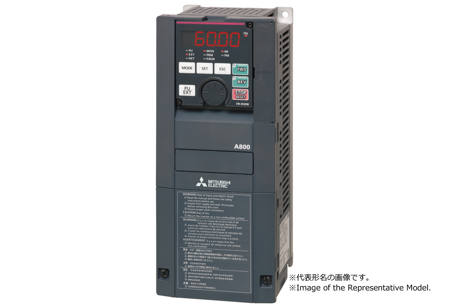
Mitsubishi Electric Corporation (Factory Automation / FA Systems Group) FR-A820-04750-1-60
FR-A820-04750-1-60
Технические характеристики
| Series | FR-A800 |
|---|---|
| Type | Three-phase 200 V class Standard model RS-485 model |
| Inverter capacity (kW) | 90.0 |
| SLD | 132.0 |
| LD | 110.0 |
| ND | 90.0 |
| HD | 75.0 |
| Output > Rated capacity (kVA) *3 > SLD | 181.0 |
| Output > Rated capacity (kVA) *3 > LD | 165.0 |
| Output > Rated capacity (kVA) *3 > ND | 132.0 |
| Output > Rated capacity (kVA) *3 > HD | 110.0 |
| Output > Rated current (A) > SLD | 475.0 |
| Output > Rated current (A) > LD | 432.0 |
| Output > Rated current (A) > ND | 346.0 |
| Output > Rated current (A) > HD | 288.0 |
| Output > Overload current rating *4 > SLD | 110 % 60 s, 120 % 3 s (inverse-time characteristics) at surrounding air temperature of 40 °C |
| Output > Overload current rating *4 > LD | 120 % 60 s, 150 % 3 s (inverse-time characteristics) at surrounding air temperature of 50 °C |
| Output > Overload current rating *4 > ND | 150 % 60 s, 200 % 3 s (inverse-time characteristics) at surrounding air temperature of 50 °C |
| Output > Overload current rating *4 > HD | 200 % 60 s, 250 % 3 s (inverse-time characteristics) at surrounding air temperature of 50 °C |
| Напряжение питания | Three-phase 200 to 240 V |
| Brake transistor | FR-BU2 (option) |
| Maximum brake torque (ND reference) | 10 % torque, continuous |
| Maximum brake torque (ND reference) (FR-ABR (when the option is used)) | - |
| Напряжение питания | Three-phase 200 to 240 V, 50/60 Hz |
| Напряжение питания | 170 to 264 V, 50/60 Hz |
| Permissible frequency fluctuation | ±5 % |
| Power supply > Rated input current (A) without DC reactor *7 > SLD | - |
| Power supply > Rated input current (A) without DC reactor *7 > LD | - |
| Power supply > Rated input current (A) without DC reactor *7 > ND | - |
| Power supply > Rated input current (A) without DC reactor *7 > HD | - |
| Power supply > Rated input current (A) with DC reactor *7 > SLD | 475.0 |
| Power supply > Rated input current (A) with DC reactor *7 > LD | 432.0 |
| Power supply > Rated input current (A) with DC reactor *7 > ND | 346.0 |
| Power supply > Rated input current (A) with DC reactor *7 > HD | 288.0 |
| Power supply > Power supply capacity (kVA) without DC reactor *8 > SLD | - |
| Power supply > Power supply capacity (kVA) without DC reactor *8 > LD | - |
| Power supply > Power supply capacity (kVA) without DC reactor *8 > ND | - |
| Power supply > Power supply capacity (kVA) without DC reactor *8 > HD | - |
| Power supply > Power supply capacity (kVA) with DC reactor *8 > SLD | 181.0 |
| Power supply > Power supply capacity (kVA) with DC reactor *8 > LD | 165.0 |
| Power supply > Power supply capacity (kVA) with DC reactor *8 > ND | 132.0 |
| Power supply > Power supply capacity (kVA) with DC reactor *8 > HD | 110.0 |
| IEC 60529 *9 | IP00 |
| Cooling system | Forced air |
| Approx. mass (kg) | 74.0 |
| Common | Soft-PWM control/High carrier frequency PWM control |
| Induction motor | Selectable among V/F control, Advanced magnetic flux vector control, Real sensorless vector control, and Vector control *10 |
| PM motor | Selectable among PM sensorless vector control, and Vector control *10 |
| Control > Output frequency range > Induction motor | 0.2 to 590 Hz (The upper-limit frequency is 400 Hz under Advanced magnetic flux vector control, Real sensorless vector control, and Vector control *10 .) |
| Control > Output frequency range > PM motor | 0.2 to 400 Hz (not operable at a frequency higher than the maximum motor frequency) |
| Analog input | 0.015 Hz/60 Hz at 0 to 10 V/12 bits (terminals 2 and 4) 0.03 Hz/60 Hz at 0 to 5 V/11 bits or 0 to 20 mA/11 bits (terminals 2 and 4), at 0 to ±10 V/12 bits (terminal 1) 0.06 Hz/60 Hz at 0 to ±5 V/11 bits (terminal 1) |
| Digital input | 0.01 Hz |
| Control > Frequency accuracy > Analog input | Within ±0.2 % of the maximum output frequency (25 °C±10 °C) |
| Control > Frequency accuracy > Digital input | 0.01 % or less of the set output frequency |
| Напряжение питания | Base frequency can be set from 0 to 590 Hz. Constant-torque/variable-torque pattern or adjustable 5 points V/F can be selected. |
| Control > Starting torque > Induction motor | The following is the specifications for the ND rating. 30 % or less at 1 Hz, 30 % at 3 Hz, 80 % at 6 Hz (V/F control) 150 % at 0.5 Hz (Advanced magnetic flux vector control) 200 % at 0.3 Hz (0.4K to 3.7K), 150 % at 0.3 Hz (5.5K or higher) (Real sensorless vector control) 200 % at 0 Hz (0.4K to 3.7K), 150 % at 0 Hz (5.5K or higher) (Vector control *10 ) |
| Control > Starting torque > PM motor | The following is the specifications for the ND rating. 50 % (current synchronization operation) 200 % (when used with MM-CF, 200 % for the 1.5 kW or lower, and 150 % for the 2.0 kW or higher) (high frequency superposition control) |
| Torque boost | Manual torque boost (induction motor only) |
| Acceleration/deceleration time setting | 0 to 3600 s (acceleration and deceleration can be set individually), linear or S-pattern acceleration/deceleration mode, backlash countermeasures acceleration/deceleration modes are available. |
| Control > DC injection brake > Induction motor | Operation frequency (0 to 120 Hz), operation time (0 to 10 s), operation voltage (0 to 30 %) variable |
| Control > DC injection brake > PM motor | Operation time (0 to 10 s) variable. Operating voltage (operating current) fixed. |
| Stall prevention operation level | Activation range of stall prevention operation (SLD rating : 0 to 120 %, LD rating : 0 to 150 %, ND rating : 0 to 220 %, HD rating : 0 to 280 %). Whether to use the stall prevention or not can be selected. (V/F control, Advanced magnetic flux vector control) |
| Torque limit level | Torque limit value can be set (0 to 400 % variable). (Real sensorless vector control, Vector control *10 , PM sensorless vector control) |
| Number of analog input | 3 |
| Specification of analog input | Terminals 2 and 4 : 0 to 10 V/0 to 5 V/4 to 20 mA (0 to 20 mA) Terminal 1 : -10 to +10 V/-5 to +5 V |
| Operation > Frequency setting signal > Digital input | Input using the setting dial of the operation panel or parameter unit. Input of four-digit BCD (Binary-coded decimal) or 16-bit binary (when the option FR-A8AX is installed). |
| Start signal | Forward and reverse rotation or start signal automatic self-holding input (3-wire input) can be selected. |
| Number of input signal (Contact input) | 12 |
| Pulse train input | 100 k pulses/s |
| Input terminal function selectable signal | Low-speed operation command, Middle-speed operation command, High-speed operation command, Second function selection, Terminal 4 input selection, Jog operation selection, Selection of automatic restart after instantaneous power failure/flying start, Output stop, Start self-holding selection, Forward rotation command, Reverse rotation command, Inverter reset The signal to be input can be changed using Pr.178 to Pr.189 (Input terminal function selection). |
| Operational function | Maximum and minimum frequency settings, Multi-speed operation, Acceleration/deceleration pattern, Thermal protection, DC injection brake, Starting frequency, JOG operation, Output stop (MRS), Stall prevention, Regeneration avoidance, Increased magnetic excitation deceleration, DC feeding, Frequency jump, Rotation display, Automatic restart after instantaneous power failure, Electronic bypass sequence, Remote setting, Automatic acceleration/deceleration, Retry function, Carrier frequency selection, Fast-response current limit, Forward/reverse rotation prevention, Operation mode selection, Slip compensation, Droop control, Load torque high-speed frequency control, Speed smoothing control, Traverse, Auto tuning, Applied motor selection, Gain tuning, RS-485 communication, PID control, PID precharge function, Easy dancer control, Cooling fan operation selection, Stop selection, Power failure time deceleration-to-stop function, Stop-on-contact control, PLC function, Life diagnosis, Maintenance timer, Current average monitor, Multiple rating, Orientation control *10 , Speed control, Torque control, Position control, Pre-excitation, Torque limit, Test run, 24 V power supply input for control circuit, Safety stop function, Anti-sway control |
| Number of output signal (Open collector output) | 5 |
| Number of output signal (Relay output) | 2 |
| Output terminal function selectable signal | Inverter running, Up to frequency, Instantaneous power failure/undervoltage, Overload warning, Output frequency detection, Fault The signal to be output can be changed using Pr.190 to Pr.196 (Output terminal function selection). Fault codes (4 bits) of the inverter can be output from the open collector. |
| Pulse train output (FM type inverter) | 50 k pulses/s |
| Number of output signal for indication on external meters | 2 |
| Indication > For indication on external meters > Pulse train output (FM type inverter) | Max. 2.4 kHz via one terminal (for the indication of inverter output frequency). The item for monitoring can be changed using Pr.54 FM/CA terminal function selection. |
| Current output (CA type inverter) | Max. 20 mA DC via one terminal (for the indication of inverter output frequency). The item for monitoring can be changed using Pr.54 FM/CA terminal function selection. |
| Напряжение питания | Max. 10 V DC via one terminal (for the indication of inverter output frequency). The item for monitoring can be changed using Pr.158 AM terminal function selection. |
| Status monitoring | Output frequency, output current, output voltage, and frequency setting value are monitored. The item for monitoring can be changed using Pr.52 Operation panel main monitor selection. |
| Fault monitoring | When a protective function is activated, a fault indication is displayed and the output voltage, output current, output frequency, cumulative energization time, date (year, month, day) and time at the occurrence of the fault are stored. Each fault is recorded and the last 8 records can be displayed. |
| Protective function | Overcurrent trip during acceleration, Overcurrent trip during constant speed, Overcurrent trip during deceleration or stop, Regenerative overvoltage trip during acceleration, Regenerative overvoltage trip during constant speed, Regenerative overvoltage trip during deceleration or stop, Inverter overload trip (electronic thermal relay function), Motor overload trip (electronic thermal relay function), Heat sink overheat, Instantaneous power failure, Undervoltage, Input phase loss *12 , Stall prevention stop, Loss of synchronism detection *12 , Brake transistor alarm detection, Upper limit fault detection, Lower limit fault detection, Output side earth (ground) fault overcurrent, Output short circuit, Output phase loss, External thermal relay operation, *12 PTC thermistor operation *12 , Option fault, Communication option fault, Parameter storage device fault, PU disconnection, Retry count excess *12 , CPU fault, Operation panel power supply short circuit/RS-485 terminals power supply short circuit, 24 VDC power fault, Abnormal output current detection *12 , Inrush current limit circuit fault, Communication fault (inverter), Analog input fault, USB communication fault, Safety circuit fault, Overspeed occurrence *12 , Speed deviation excess detection *10 *12 , Signal loss detection *10 *12 , Excessive position fault *10 *12 , Brake sequence fault *12 , Encoder phase fault *10 *12 , 4 mA input fault *12 , Pre-charge faul *12 t, PID signal fault *12 , Option fault, Opposite rotation deceleration fault *12 , Internal circuit fault, Magnetic pole position unknown *10 , External fault during output operation *12 |
| Warning function | Fan alarm, Stall prevention (overcurrent), Stall prevention (overvoltage), Regenerative brake pre-alarm *12 , Electronic thermal relay function pre-alarm, PU stop, Speed limit indication *12 , Parameter copy, Safety stop, Maintenance timer *12 , USB host error, Home position return setting error *12 , Home position return uncompleted *12 , Home position return parameter setting error *12 , Operation panel lock *12 , Password locked *12 , Parameter write error, Copy operation error, 24 V external power supply operation, Continuous operation during communication fault *12 , Load fault warning |
| Surrounding air temperature | -10 °C to +50 °C (non-freezing) (LD, ND, HD ratings) -10 °C to +40 °C (non-freezing) (SLD rating) |
| Surrounding air humidity | 95 % RH or less (non-condensing) |
| Storage temperature *13 | -20 °C to +65 °C |
| Ambience | Indoors (free from corrosive gas, flammable gas, oil mist, dust and dirt) |
| Altitude/vibration | Maximum 2500 m *14 , 5.9 m/s 2 or less at 10 to 55 Hz in X, Y, and Z directions |
| Network | RS-485 : Mitsubishi inverter protocol, MODBUS RTU Option unit : CC-Link IE TSN, CC-Link IE Field Network, CC-Link, SSCNETIII(/H), DeviceNet, PROFIBUS-DPV0, FL remote, EtherCAT, EtherNet/IP, PROFINET, PROFIBUS-DPV1 |
| Category (site listing) | FR-A800 |