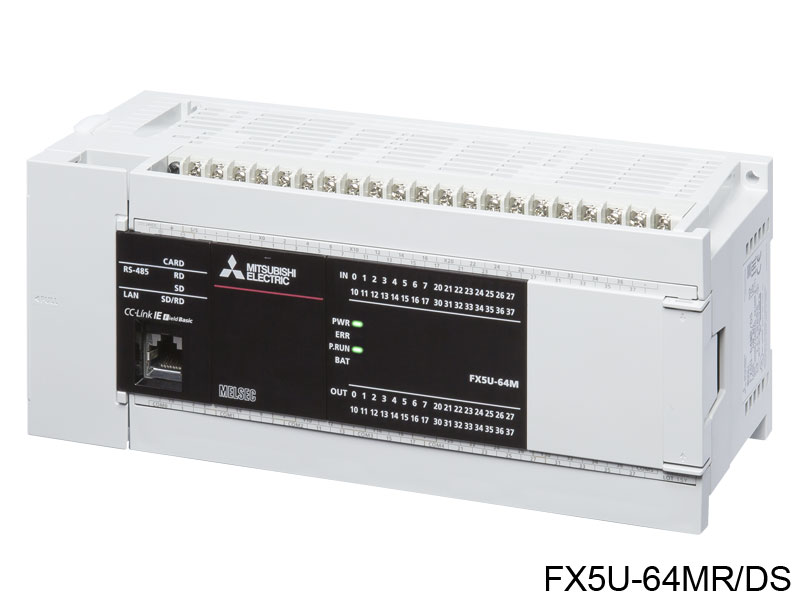
Mitsubishi Electric Corporation (Factory Automation / FA Systems Group) FX5U-64MR/DS
FX5U-64MR/DS
Технические характеристики
| Control system | Stored-program repetitive operation |
|---|---|
| Input/output control system | Refresh system (Direct access input/output allowed by specification of direct access input/output [DX, DY]) |
| (1) No. of input/output points | 256 points or less/384 points or less* *Supported with CPU module firmware version 1.100 and later. In addition, GX Works3 version 1.047Z and later is required. |
| (2) No. of remote I/O points | 384 points or less/512 points or less* *Supported with CPU module firmware version 1.100 and later. In addition, GX Works3 version 1.047Z and later is required. |
| Total No. of points of (1) and (2) | 512 points or less |
| Programming language | Ladder diagram (LD), structured text (ST), function block diagram/ladder diagram (FBD/LD), sequential function chart (SFC)* *For supported versions, refer to MELSEC iQ-F FX5 User's Manual (Application). |
| Programming extension function | Function block (FB), function (FUN), label programming (local/global) |
| Constant scan | Keeps the scan time constant and executes program repeatedly. |
| Fixed cycle interrupt | 1 to 60000 ms (can be set in 1 ms increments) |
| Timer performance specifications | 100 ms, 10 ms, 1 ms |
| No. of program executions | 32 |
| No. of FB files | 16 (Up to 15 for user) |
| Execution type | Standby type, initial execution type, scan execution type, fixed scan execution type, event execution type |
| Interrupt type | Internal timer interrupt, input interruption, high-speed comparison match interrupt, interrupt by modules* *Interrupt from the intelligent function module and high-speed pulse input/output module. |
| LD X0 | 34 ns* *When the program capacity is 64 k steps. |
| MOV D0 D1 | 34 ns* *When the program capacity is 64 k steps. |
| Program capacity | 64 k steps/128 k steps* (128 kbytes/256 kbytes, flash memory) *Supported with CPU module firmware version 1.100 or later. In addition, GX Works3 version 1.047Z or later is required. |
| SD memory card | Memory card capacity (SD/SDHC memory card: Max. 16 Gbytes) |
| Device/label memory | 120 kbytes |
| Data memory/standard ROM | 5 Mbytes |
| Flash memory (Flash ROM) write count | Maximum 20000 times |
| File storage capacity > Device/label memory | 1 |
| P: No. of program files | 32 |
| FB: No. of FB files | 16 |
| 2 Gbytes | 511 The number of files stored in the root folder. |
| 4 Gbytes, 8 Gbytes, 16 Gbytes | 65534 The number of files stored in the root folder. |
| Display data | Year, month, day, hour, minute, second, day of week (leap year automatic detection) |
| Precision | Differences per month ±45 sec./25℃ (TYP) |
| Retention method | Large-capacity capacitor Clock data is retained using the power accumulated in a large-capacity capacitor incorporated into the PLC. When voltage of the large-capacity capacitor drops, clock data is no longer accurately retained. The retention period of a fully charged capacitor (electricity is conducted across the PLC for at least 30 minutes) is 10 days (ambient temperature: 25℃). How long the capacitor can hold the data depends on the operating ambient temperature. When the operating ambient temperature is high, the holding period is short. |
| Retention time | 10 days (Ambient temperature: 25℃) |
| Power failure retention capacity | Maximum 12 k word It is possible to back up all devices in device (high-speed) area. When a battery is used, it is also possible to back up devices in device (standard) area. |
| Octal | 1024 points The total number of X and Y assigned to I/O points is up to 256 points/384 points* *Supported with CPU module firmware version 1.100 or later. In addition, GX Works3 version 1.047Z or later is required. |
| Decimal | 32768 points (can be changed with parameter) Can be changed with parameters within the capacity range of the CPU built-in memory. |
| Hexadecimal | 32768 points (can be changed with parameter) Can be changed with parameters within the capacity range of the CPU built-in memory. |
| No. of user device points > Step relay (S) > Decimal | 4096 points (fixed) |
| No. of user device points > Timer system (Timer (T)) > Decimal | 1024 points (can be changed with parameter) Can be changed with parameters within the capacity range of the CPU built-in memory. |
| No. of user device points > Accumulation timer system (Accumulation timer (ST)) > Decimal | 1024 points (can be changed with parameter) Can be changed with parameters within the capacity range of the CPU built-in memory. |
| No. of user device points > Counter system (Counter (C)) > Decimal | 1024 points (can be changed with parameter) Can be changed with parameters within the capacity range of the CPU built-in memory. |
| No. of user device points > Counter system (Long counter (LC)) > Decimal | 1024 points (can be changed with parameter) Can be changed with parameters within the capacity range of the CPU built-in memory. |
| No. of user device points > Data register (D) > Decimal | 8000 points (can be changed with parameter) Can be changed with parameters within the capacity range of the CPU built-in memory. |
| No. of system device points > Special relay (SM) > Decimal | 10000 points (fixed) |
| No. of system device points > Special register (SD) > Decimal | 12000 points (fixed) |
| Module access device > Intelligent function module device > Decimal | 65536 points (designated by U□\G□) |
| No. of index register points > Index register (Z) > Decimal | 24 points The sum of index register (Z) and long index register (LZ) is 24 words. |
| No. of index register points > Long index register (LZ) > Decimal | 12 points The sum of index register (Z) and long index register (LZ) is 24 words. |
| No. of file register points > Extended file register (ER) > Decimal | 32768 points (are stored in SD memory card) |
| No. of nesting points > Nesting (N) > Decimal | 15 points (fixed) |
| No. of pointer points > Pointer (P) > Decimal | 4096 points |
| No. of pointer points > Interrupt pointer (I) > Decimal | 178 points (fixed) |
| Signed | 16 bits: -32768 to +32767 32 bits: -2147483648 to +2147483647 |
| Unsigned | 16 bits: 0 to 65535 32 bits: 0 to 4294967295 |
| Hexadecimal constant (H) | 16 bits: 0 to FFFF 32 bits: 0 to FFFFFFFF |
| Single precision | E-3.40282347+38 to E-1.17549435-38, 0, E1.17549435-38 to E3.40282347+38 |
| Character string | Shift-JIS code max. 255 single-byte characters (256 including NULL) |
| Напряжение питания | 24 V DC |
| Напряжение питания | -30%, +20% |
| Frequency rating | - |
| Allowable instantaneous power failure time | Operation can be continued upon occurrence of instantaneous power failure for 5 ms or less. |
| Power fuse | 250 V, 5 A Time-lag fuse |
| Rush current | 65 A max. 2.0 ms or less/24 V DC |
| Power consumption | 40 W Maximum consumption value when using the maximum configuration connectable to the CPU module. |
| 24 V DC built-in power supply capacity | 740 mA (530 mA) The value in () is capacity of power supply when the supply voltage is 16.8-19.2 V DC. |
| 5 V DC built-in power supply capacity | 1100 mA (975 mA) The value in () is capacity of power supply when the supply voltage is 16.8-19.2 V DC. |
| No. of input points | 32 points |
| Input connection type | Removable terminal block (M3 screws) |
| Input type | Sink/source |
| Напряжение питания | 24 V DC +20%, -15% |
| X0 to X17 | 5.3 mA/24 V DC |
| X20 and subsequent | 4.0 mA/24 V DC |
| Input impedance > X0 to X17 | 4.3 kΩ |
| Input impedance > X20 and subsequent | 5.6 kΩ |
| ON input sensitivity current > X0 to X17 | 3.5 mA or more |
| ON input sensitivity current > X20 and subsequent | 3.0 mA or more |
| OFF input sensitivity current | 1.5 mA or less |
| X0 to X7 | 200 kHz When capturing pulses of a response frequency of 50 to 200 kHz, refer to MELSEC iQ-F FX5S/FX5UJ/FX5U/FX5UC User's Manual (Hardware). |
| X10 to X17 | 10 kHz |
| Input response frequency > X20 and subsequent | 0.1±0.05 kHz |
| Pulse waveform > X0 to X7 | T1 (pulse width): 2.5 μs or more T2 (rise/fall time): 1.25 μs or less |
| Pulse waveform > X10 to X17 | T1 (pulse width): 50 μs or more T2 (rise/fall time): 25 μs or less |
| Время отклика | ON: 2.5 μs or less OFF: 2.5 μs or less |
| Время отклика | ON: 30 μs or less OFF: 50 μs or less |
| Время отклика | ON: 50 μs or less OFF: 150 μs or less |
| Время отклика | None, 10 μs, 50 μs, 0.1 ms, 0.2 ms, 0.4 ms, 0.6 ms, 1 ms, 5 ms, 10 ms (initial values), 20 ms, 70 ms When using this product in an environment with much noise, set the digital filter. |
| Input signal format (Input sensor form) | No-voltage contact input Sink: NPN open collector transistor Source: PNP open collector transistor |
| Input circuit insulation | Photo-coupler insulation |
| Indication of input operation | LED is lit when input is on |
| No. of output points | 32 points |
| Output connection type | Removable terminal block (M3 screws) |
| Output type | Relay output |
| External power supply | 30 V DC or less 240 V AC or less ("250 V AC or less" if not a CE, UL, cUL compliant item) |
| Max. load | 2 A/point The total load current per common terminal should be the following value. 4 output points/common terminal: 8 A or less 8 output points/common terminal: 8 A or less |
| Min. load | 5 V DC, 2 mA (reference values) |
| Open circuit leakage current | - |
| OFF→ON | Approx. 10 ms |
| ON→OFF | Approx. 10 ms |
| Output circuit insulation | Mechanical insulation |
| Indication of output operation | LED is lit when output is on |
| Firmware update function | This function updates the module's firmware using an SD memory card. |
| Scan monitoring function (Watchdog timer setting) | Detects an error in the hardware and program of the CPU module by monitoring the scan time. |
| Clock function | This function is used for the time management in the function which the system operates such as the date of the event history function, and data logging function. |
| Online ladder block change | Writes the part of a program edited on the ladder editor using the engineering tool to the CPU module in units of ladder blocks. Edited contents spanning multiple portions can be written to the CPU module at once. |
| Multiple interrupt function | When an interrupt occurs while an interrupt program triggered by another cause is running, stops the program if its priority is lower than that of the new interrupt, and runs the higher-priority program whenever its execution condition is satisfied. |
| PID control function | Performs PID control by the PID control instruction. |
| Remote RUN/STOP | Changes the CPU module status to the RUN/STOP/PAUSE status externally while the RUN/STOP/RESET switch of the CPU module is in RUN status. |
| Remote PAUSE | Changes the CPU module status to the RUN/STOP/PAUSE status externally while the RUN/STOP/RESET switch of the CPU module is in RUN status. |
| Remote RESET | Resets the CPU module externally while the CPU module is in the STOP status. |
| Device/label memory area setting | Sets the capacity of each area in the device/label memory. |
| Program capacity setting | Set to change program capacity. |
| Internal buffer capacity setting | Sets the capacity of the area (internal buffer) used by the system to temporarily store the results of data logging and memory dump processing. |
| Initial device value setting | Sets the initial values of devices used in the program directly (not via the program) to the devices. |
| Latch function | Holds the contents of the device and label of the CPU module when the power is turned ON etc. |
| SD memory card forced stop | Makes the SD memory card unavailable without turning OFF the power even when the function accessing the SD memory card is executed. |
| Boot operation | Transfers the file stored in the SD memory card to the transfer destination memory judged automatically by the CPU module when the power is turned ON or is reset. |
| Device/label access service processing setting | Sets the number of execution times of the device/label access service processing executed by END processing, with parameter. |
| Data logging function | Collects data at the specified interval or any desired timing, and stores them as a file on the SD memory card. |
| Memory dump function | Saves the data in the devices of the CPU module at a desired timing. |
| Real-time monitor function | Monitors the data in the specified device of the CPU module at a specified interval or at a desired timing in real time. |
| Self-diagnostics function | Self-diagnoses the CPU module to see whether an error exist or not. |
| Error clear | Batch-clears all the continuation errors being detected. |
| Event history function | Collects operations executed and errors detected from the modules, and saves them in the CPU module, expansion board, expansion adapter, and intelligent module. The saved logs can be checked in chronological order. |
| Data backup/restoration function | Backs up program files, parameter files, and device/label data files in a CPU module to an SD memory card. The backup data can be restored as needed. |
| Security function | Protects resources stored in PCs and resources in the units in the system of the FX5 from illegal access by a third party such as theft, alteration, accidental operation and unauthorized execution. |
| IP filter function | Identifies the IP address of external devices over Ethernet, and blocks access from an invalid IP address. |
| High-speed counter function | Performs high-speed counter, pulse width measurement, input interruption, etc. by using the input of the CPU module or high-speed pulse input/output module. |
| Pulse width measurement function | Performs high-speed counter, pulse width measurement, input interruption, etc. by using the input of the CPU module or high-speed pulse input/output module. |
| Input interrupt function | Performs high-speed counter, pulse width measurement, input interruption, etc. by using the input of the CPU module or high-speed pulse input/output module. |
| Positioning function | Executes positioning operation by using the transistor output of the high-speed pulse input/output module. |
| PWM output function | Executes a PWM output by using the transistor output of the high-speed pulse input/output module. |
| Analog input function | Two analog inputs are built in the FX5U CPU module so that voltage input can be performed. |
| Analog output function | One analog output are built in the FX5U CPU module so that voltage output can be performed. |
| Built-in Ethernet function | An Ethernet related function such as connection to MELSOFT products and GOTs, socket communication, file transfer using FTP, Web server (HTTP), SNTP client, and simple CPU communication function. |
| CC-Link IE Field Network Basic function | This function exchanges data between the manager station and remote station using general-purpose Ethernet. |
| Serial communication function | A function related to the serial communication such as N:N Network, parallel link, MC protocol, inverter communication function and non-protocol communication. |
| MODBUS communication function | Connection with the products which support MODBUS RTU/TCP is available. The master and slave functions can be used. |
| Рабочая температура | -20 to 55℃, non-freezing The simultaneous ON ratio of available PLC inputs or outputs changes with respect to the ambient temperature, refer to MELSEC iQ-F FX5S/FX5UJ/FX5U/FX5UC User's Manual (Hardware). The operating ambient temperature is 0 to 55℃ for products manufactured before June 2016. For details on Intelligent function modules, refer to manuals of each product. In the case where operating ambient temperature is lower than 0℃, the specifications are different from the above description. For details, refer to MELSEC iQ-F FX5S/FX5UJ/FX5U/FX5UC User's Manual (Hardware). |
| Storage ambient temperature | -25 to 75℃, non-freezing |
| Operating ambient humidity | 5 to 95%RH, non-condensation When used in a low-temperature environment, use in an environment with no sudden temperature changes. If there are sudden temperature changes because of opening/closing of the control panel or other reasons, condensation may occur, which may cause a fire, fault, or malfunction. Furthermore, use an air conditioner in dehumidifier mode to prevent condensation. |
| Storage ambient humidity | 5 to 95%RH, non-condensation |
| Frequency: 5 to 8.4 Hz | Half amplitude: 1.75 mm 10 times each in X, Y, Z directions (80 min in each direction) The criterion is shown in IEC61131-2. When the system has equipment which specification values are lower than above mentioned vibration resistance specification values, the vibration resistance specification of the whole system is corresponding to the lower specification. |
| Frequency: 8.4 to 150 Hz | Acceleration: 4.9 m/s 2 10 times each in X, Y, Z directions (80 min in each direction) The criterion is shown in IEC61131-2. When the system has equipment which specification values are lower than above mentioned vibration resistance specification values, the vibration resistance specification of the whole system is corresponding to the lower specification. |
| Vibration resistance > Direct installing > Frequency: 5 to 8.4 Hz | Half amplitude: 3.5 mm 10 times each in X, Y, Z directions (80 min in each direction) The criterion is shown in IEC61131-2. When the system has equipment which specification values are lower than above mentioned vibration resistance specification values, the vibration resistance specification of the whole system is corresponding to the lower specification. |
| Vibration resistance > Direct installing > Frequency: 8.4 to 150 Hz | Acceleration: 9.8 m/s 2 10 times each in X, Y, Z directions (80 min in each direction) The criterion is shown in IEC61131-2. When the system has equipment which specification values are lower than above mentioned vibration resistance specification values, the vibration resistance specification of the whole system is corresponding to the lower specification. |
| Shock resistance | 147 m/s 2 , Action time: 11 ms, 3 times by half-sine pulse in each direction X, Y, and Z The criterion is shown in IEC61131-2. |
| Noise durability | By noise simulator at noise voltage of 1000 Vp-p, noise width of 1 μs and period of 30 to 100 Hz |
| Between power supply terminal (DC power supply) and ground terminal | 500 V AC for one minute |
| Between input terminal (24 V DC) and ground terminal | 500 V AC for one minute |
| Between output terminal (relay) and ground terminal | 1.5 kV AC for one minute |
| Insulation resistance > Between power supply terminal (DC power supply) and ground terminal | 10 MΩ or higher by 500 V DC insulation resistance tester |
| Insulation resistance > Between input terminal (24 V DC) and ground terminal | 10 MΩ or higher by 500 V DC insulation resistance tester |
| Insulation resistance > Between output terminal (relay) and ground terminal | 10 MΩ or higher by 500 V DC insulation resistance tester |
| Grounding | Class D grounding (grounding resistance: 100 Ω or less) (Common grounding with a heavy electrical system is not allowed) For grounding, refer to MELSEC iQ-F FX5S/FX5UJ/FX5U/FX5UC User's Manual (Hardware). |
| Working atmosphere | Free from corrosive or flammable gas and excessive conductive dust |
| Operating altitude | 0 to 2000 m The PLC cannot be used at a pressure higher than the atmospheric pressure to avoid damage. |
| Installation location | Inside a control panel The programmable controller is assumed to be installed in an environment equivalent to indoor. |
| Напряжение питания | II or less This indicates the section of the power supply to which the equipment is assumed to be connected between the public electrical power distribution network and the machinery within premises. Category II applies to equipment for which electrical power is supplied from fixed facilities. The surge voltage withstand level for up to the rated voltage of 300 V is 2500 V. |
| Pollution degree | 2 or less This index indicates the degree to which conductive material is generated in the environment in which the equipment is used. Pollution level 2 is when only non-conductive pollution occurs. Temporary conductivity caused by condensation must be expected occasionally. |
| Category (site listing) | CPU Module |