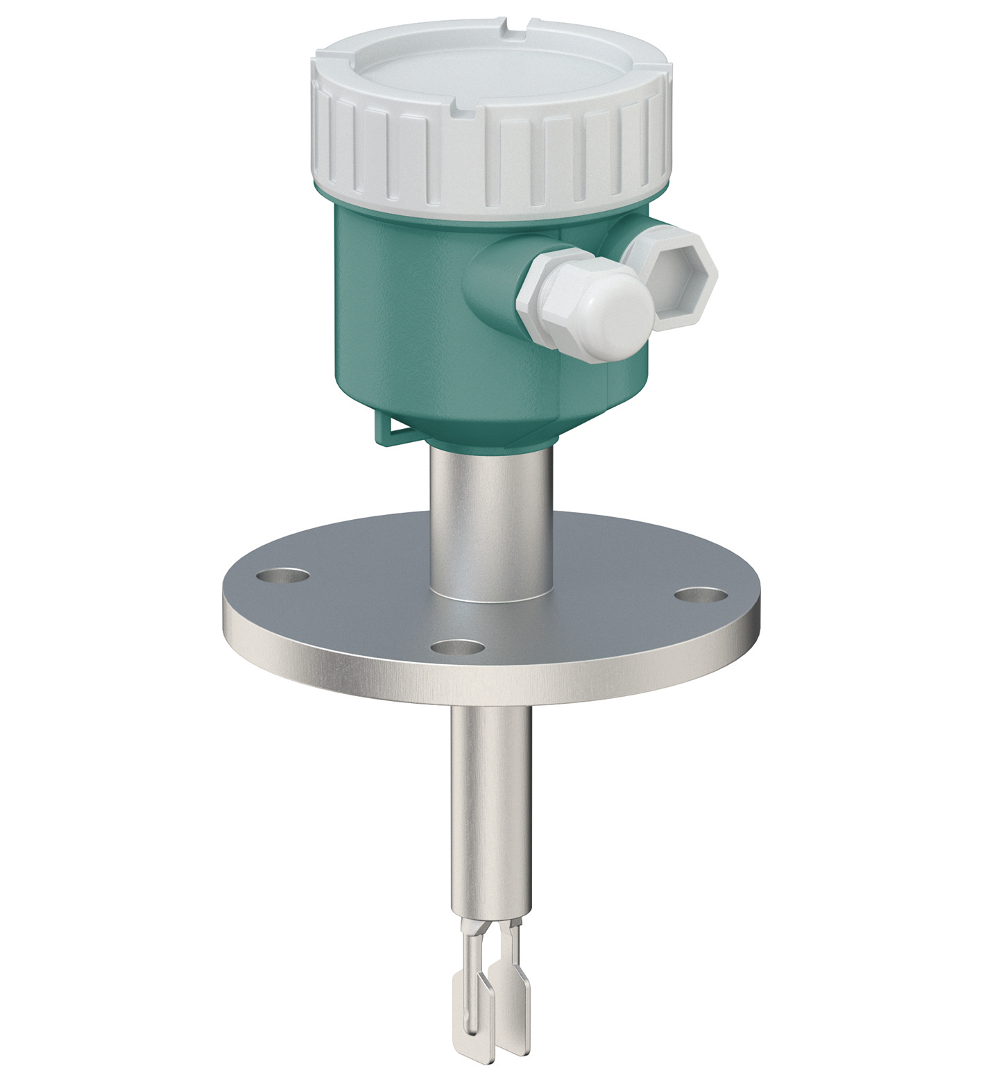
Pepperl+Fuchs SE LVL-M4-B
Vibration Limit Switch with Short Tube
Технические характеристики
| Function principle | point level detection, maximum or minimum detection for liquids |
|---|---|
| Measuring method | The change in vibration frequency causes the device to switch. |
| Construction type | device with short tube |
| Series | Vibracon LVL-M4 |
| Housing | single compartment, aluminum, coatedsingle compartment, 316L, castsingle compartment, plasticdual compartment, L-shape, aluminum, coated |
| Safety Integrity Level (SIL) | SIL 3 |
| Напряжение питания | electronic insert FEL61: 19 ... 253 V AC, 50/60 Hzelectronic insert FEL62: 10 V DC ... 55 V DCelectronic insert FEL64: 19 V AC ... 253 V AC50/60 Hz / 19 V DC ... 55 V DCelectronic insert FEL64DC: 9 V DC ... 20 V DCelectronic insert FEL68: switch amplifier acc. to IEC 60947-5-6 (NAMUR) |
| Current consumption | electronic insert FEL61: ≤ 3.8 mAelectronic insert FEL62: ≤ 10 mA, without load |
| Power consumption | electronic insert FEL61: ≤ 2 VAelectronic insert FEL62: ≤ 0.5 Welectronic insert FEL64: ≤ 25 VA/< 1.3 Welectronic insert FEL64DC: < 1.0 Welectronic insert FEL68: acc. to IEC 60947-5-6 (NAMUR) |
| Interface type | Bluetooth®, optional |
| Detection range | max. 25 m |
| Configuration | commissioning, operation and maintenance via P+F Level app- can be activated/deactivated- password encryption |
| Communication | connection for LED module VU120 and Bluetooth module VU121 , optionalBluetooth wireless technology , optional |
| Switching point | see section switch point |
| Measured variable | limit level (limit value) |
| Measuring range | depends on installation location and the tube extensionmaxmum sensor length : 6 m |
| Output type | electronic insert FEL61: 2-wire with test buttonelectronic insert FEL62: 3-wire PNP with test buttonelectronic insert FEL64: relay DPDT with test buttonelectronic insert FEL64DC: relay DPDT with contact and test buttonelectronic insert FEL68: 2-wire NAMUR with test button |
| Switch behaviour | switch-over for minimum/maximum residual current safety on electronic insertMAX = maximum safety:The output switches to the power fail response when the fork is covered.for use with overspill protection for exampleMIN = minimum safety:The output switches to the power fail response when the fork is exposed.for use with dry running protection for example |
| Electromagnetic compatibility - Directive 2014/30/EU | EN 61326 |
| Напряжение питания | EN 61010-1 |
| Electromagnetic compatibility | NE 21 |
| Degree of protection | plug M12 : IP66/67, NEMA type 4XOthers : IP66/68, NEMA type 4X/6P |
| Shock resistance | IEC 60068-2-27 |
| Vibration resistance | EN 60068-2-64 |
| Climate class | IEC 60068-2-38 test Z/AD |
| Corrosion resistance | acc. to ISA-71.04, severity level G3 |
| Medium density | adjustment on the electronic insert > 0,5 g/cm3or > 0,7 g/cm3(other on request) |
| Reference operating conditions | ambient temperature: 23 °C (73 °F)process temperature: 23 °C (73 °F)density: 1 g/cm3(water)medium viscosity: 1 mPa·sprocess pressure: ambietn pressure/unpressurizedsensor installation: verticaly from abovedensity selection switch: > 0.7 g/cm3switch direction of sensor: uncovered to covered |
| Maximum measured error | max. ± 1 mm |
| Hysteresis | typ. 2.5 mm |
| Influence of medium density | see technical information (TI) |
| Influence of medium temperature | max. +1.4 ... -2.6 mm (-50 ... 150 °C (-58 ... 302 °F)) |
| Influence of medium pressure | max. 0 ... 2.6 mm (-1 ... 64 bar) |
| Installation conditions - Installation position | any position |
| Process conditions - Medium temperature | -50 ... 150 °C (-58 ... 302 °F) |
| Process conditions - Medium pressure | pe= 0 ... 100 bar (0 ... 1450.4 psi) over the entire temperature range , exceptions see process connections |
| Process conditions - Test pressure | PN = 64 bar (928 psi): test pressure = 1.5 x PN maximum 100 bar (1450 psi) depending on process connection selectedPN = 100 bar (1450 psi): test pressure = 1.5 x PN maximum 150 bar (2175 psi) depending on process connection selected |
| Process conditions - Thermal shock resistance | ≤ 120 K/s |
| Process conditions - State of aggregation | liquid |
| Process conditions - Density | min. 0.5 g/cm3, optional 0.4 g/cm3 |
| Process conditions - Viscosity | max. 10000 mm2/s (max. 10000 cSt) |
| Рабочая температура | -60 ... 70 °C (-76 ... 158 °F)For further information see technical information (TI). |
| Storage temperature | -40 ... 80 °C (-40 ... 176 °F) |
| Altitude | ≤ 2000 m above MSL |
| Connection | gland M20thread M20 , G1/2 , NPT1/2 , NPT3/4plug M12 |
| Материал | see technical information (TI) |
| Surface quality | Ra< 3.2 µm/126 µinch |
| Mass | basic weight: 0.65 kgthe basic weight comprises:- sensor (compact)- electronic insert- housing: single compartment, plastic with cover- process connection: thread, G3/4in addition to the basic weight:- modules: 0,1 kg- housing: single compartment, aluminum, coated: 0.8 kg, single compartment, 316L: 1.21 kg, dual compartment, L-shaped, aluminum, coated: 1.22 kg- temperature spacer: 0.6 kg- pressure-tight feed through: 0.7 kg- pipe extension: 1000 mm: 0.9 kg, 100 inch: 2.3 kg- plastic protective cover: 0.2 kgFor further information see technical information (TI). |
| Dimensions | housing: diameter max. 147 mm, heigth max. 163 mmtemperature spacer, pressure-tight feed through: additional length 140 mmcompact version: length depends on process connectionshort tube version: length 99 ... 118 mm, depends on process connectionpipe extension:- length 117 ... 6000 mm, 316L- length 148 ... 3000 mm, Alloy C22tuning fork: width 17.2 mm, fork width 10 mm, length 40 mmFor further information see technical information (TI). |
| Process connection | cylindrical threads G3/4, G1 acc. to DIN ISO 228 G for installing in weld-in adaptercylindrical threads G3/4, G1 acc. to DIN ISO 228 G with flat sealconical threads NPT3/4, NPT1 acc. to ANSI B 1.20.3conical threads R3/4, R1 acc. to EN 10226flanges RF, RJF, FF from 1 inch acc. to ASME B16.5flanges form A, B1, C, D, E from DN25 acc. to EN 1092-1flanges RF from 10K 25A acc. to JIS B2220Tri-Clamp from DN25 acc. to ISO 2852For further information see technical information (TI). |
| Сертификация | see instruction manuals |
| CSA approval | see instruction manuals |
| IECEx approval | see instruction manuals |
| Display elements | Standard: without displayLED module VU120, optionalBluetooth module VU121, optional |
| Control elements | switches on the electronic insert |
| Function test | via switches on the electronic inserttest magnet , optional |
| Overspill protection | see approval (ZE) |
| Supplementary documentation | technical information (TI)manuals, brief instructions (BA, KA)instruction manualsFunctional safety manuals (FY)Special documentation (SD) |
| Supplementary information | Observe the certificates, declarations of conformity, instruction manuals, and manuals where applicable. For information see www.pepperl-fuchs.com. |
| Designation | see technical information (TI) |